An inertial measurement unit (IMU) is an electronic device that measures and reports a vehicles’s specific force, angular rate, and the orientation of the robot, using a combination of accelerometers, gyroscopes, and sometimes magnetometers.
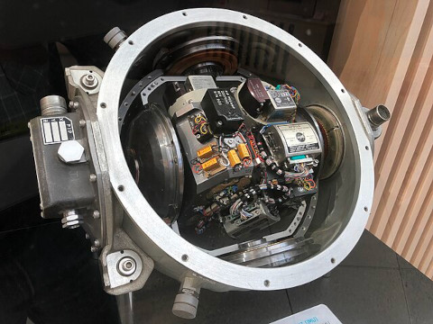
Apollo Inertial Measurement Unit
IMUs are typically used to maneuver modern vehicles including motorcycles, missiles, aircraft (an attitude and heading reference system), including uncrewed aerial vehicles (UAVs), among many others, and spacecraft, including satellites and landers.
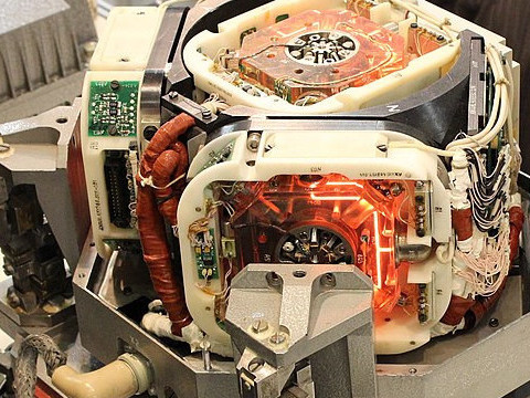
Laser Based Inertial Measurement Unit
Recent developments allow for the production of IMU-enabled GPS devices. An IMU allows a GPS receiver to work when GPS-signals are unavailable, such as in tunnels, inside buildings, or when electronic interference is present.
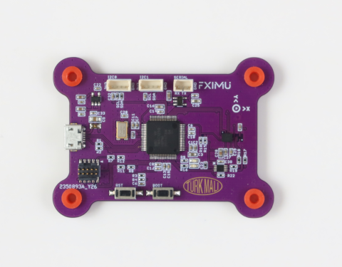
FXIMU Inertial Measurement Unit
A ROS IMU sensor perpetually measures accelerometer, gyro, and magnetometer sensors and calculates an orientation using a filtering algorithm and publishes as an Imu message.
Here is the Imu message definition
std_msgs/msg/Header header
geometry_msgs/msg/Quaternion orientation
geometry_msgs/msg/Vector3 angular_velocity
geometry_msgs/msg/Vector3 linear_acceleration
double[9] orientation_covariance
double[9] angular_velocity_covariance
double[9] linear_acceleration_covariance
header field holds the timestamp and measurement frameorientation field holds a geometry_msgs/Quaternion object, x, y, z and wangular_velocity holds the raw gyro data in 3D: x, y, zlinear_acceleration holds the raw acceleration data in 3D: x,y,zWhen we say orientation we refer to roll, pitch, yaw of an object, in our case a robot. However in modern robotics this notation is no longer used because it is prone to a mathematical error known as gimbal lock. In ROS, orientations are represented as geometry_msgs/Quaternion message, which consists of a vector x, y, z and a rotation w.
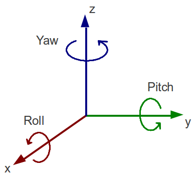
Gimbal lock is the loss of one degree of freedom in a multi-dimensional mechanism at certain alignments of the axes. In a three-dimensional three-gimbal mechanism, gimbal lock occurs when the axes of two of the gimbals are driven into a parallel configuration, locking the system into rotation in a degenerate two-dimensional space. This is a mathematical problem, and any algorithm using roll pitch yaw is affected by it.
An IMU sensor can output data in North-East-Down (NED) or East-North-Up (ENU) conventions.
IMU generally outputs data with imu_link frame_id for Imu message and mag_link frame_id for the MagneticField message.
The URDF of your robot should include a mapping between imu_link and base_link and this mapping should be broadcasted on /tf, this way any program that reads the imu data knows its relation to robots axis.
Depending on where and which orientation the imu sensor is mounted on the robot, data transformations might be necessary.
To visualize orientation you need the rviz-imu-plugin.
Start RVIZ and from left bottom of the screen click add button. Select /imu/data from the menu and add. From the top left of the screen, Global Options > Fixed Frame to ‘imu_link`. RVIZ should visualize the data as below:
ros2 run rqt_plot rqt_plot will start the rqt_plot program.
From the top of the window, write /imu/data/linear_acceleration/x in the topic box, then click add. Repeat the process for /imu/data/linear_acceleration/y and /imu/data/linear_acceleration/z. As sensor is flipped, we see that y axis goes between +/-10g. This is due to the gravity switching between different sensor axises.
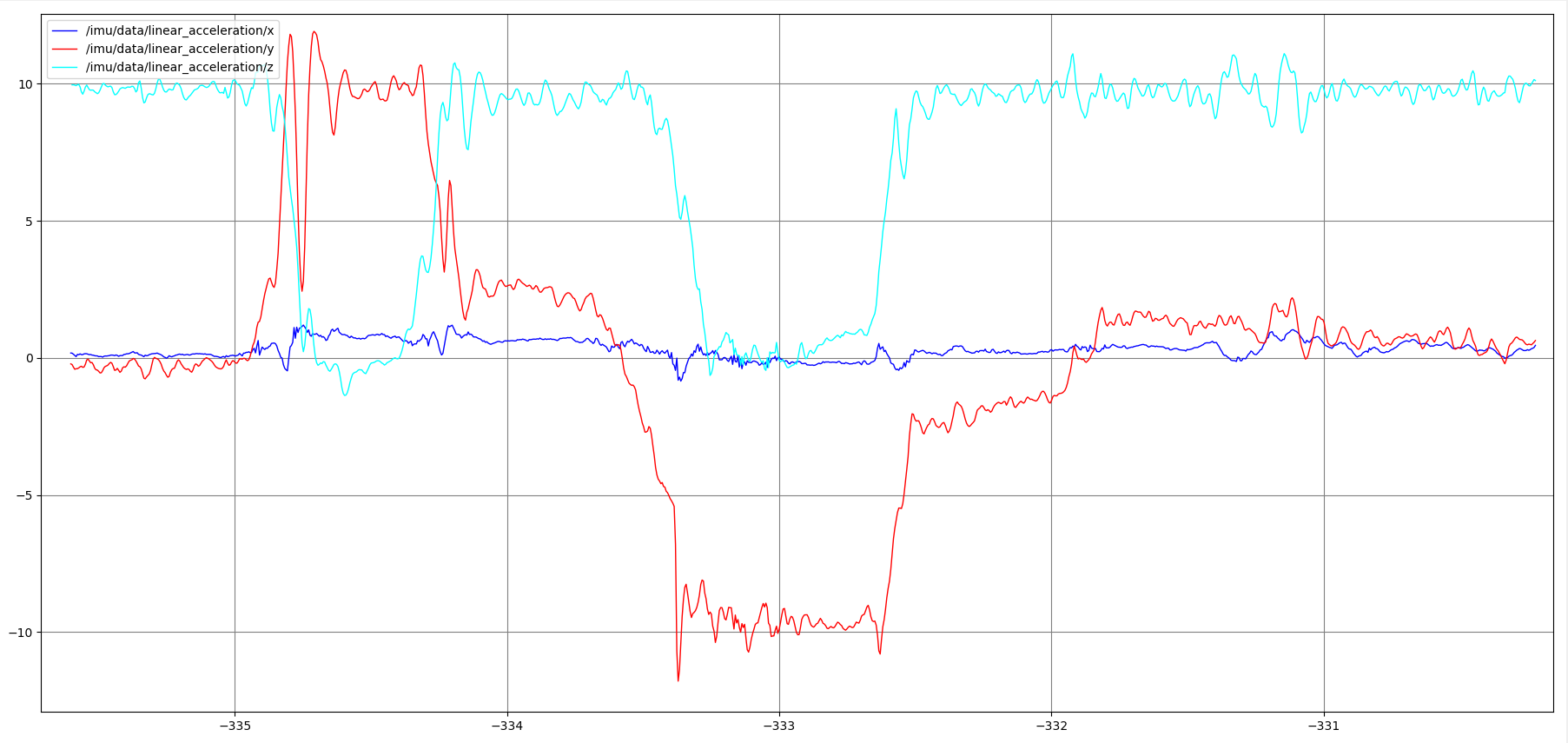 accelerometer plot in x,y,z axis while the imu sensor is flipped
From the top of the window, write /imu/data/angular_velocity/x in the topic box, then click add. Repeat the process for /imu/data/angular_velocity/y and /imu/data/angular_velocity/z. As the sensor is flipped, we see a strong change in angular_velocity/x and not the others.
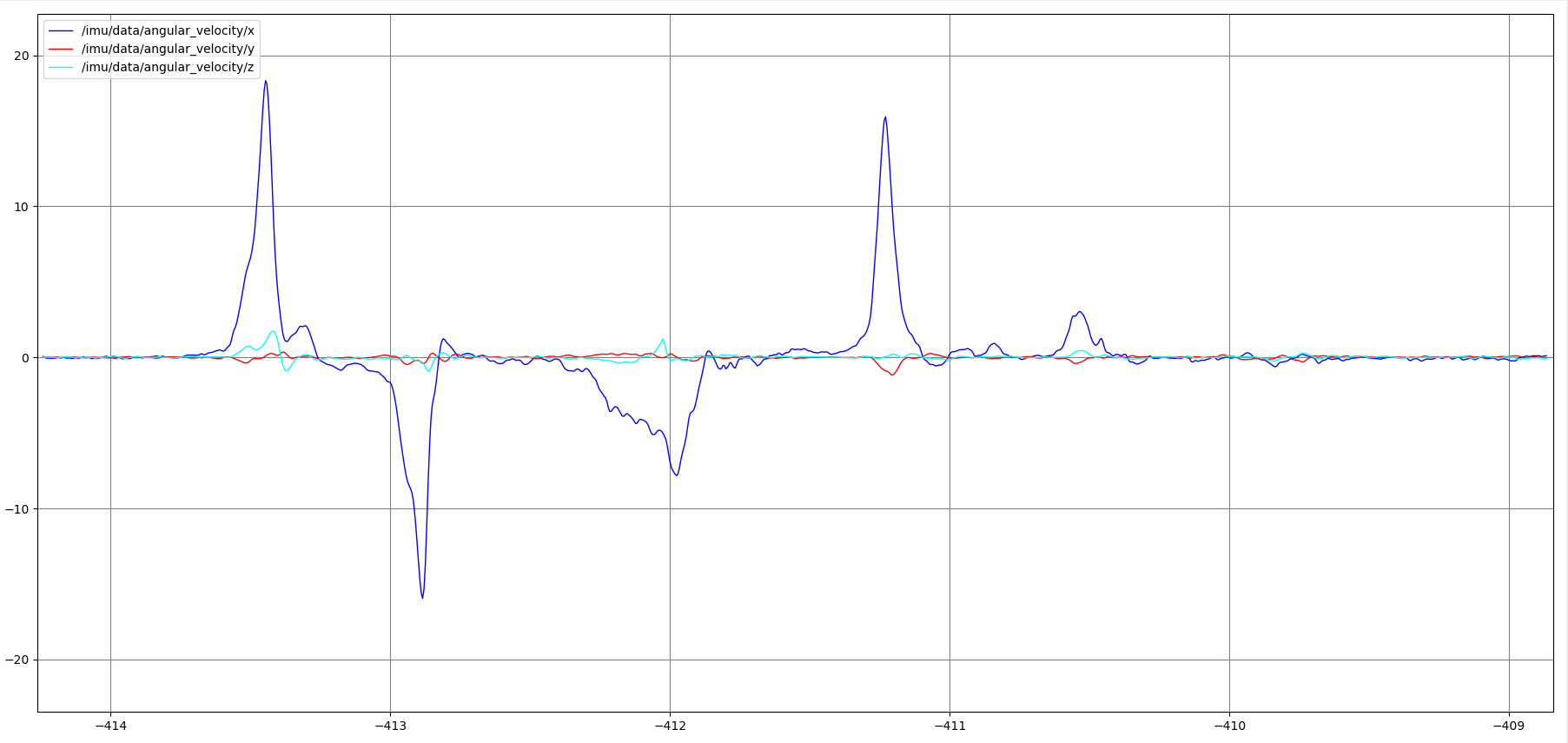 gyro data plot of x,y,z while the imu sensor is flipped
meters / second squared for the Z axis.meters / second squared for the Y axis.meters / second squared second squared for the X axis.Odometry data must also contain the covariance matrices. Covariance matrics are important for Extended Kalman Filtering performed by robot_localization node. Without acceptable covariance matrices, robot_localization node will not generate output.
https://en.wikipedia.org/wiki/Inertial_measurement_unit
Next Section: Localization