ACADA Robotics • Documentation • ROSRider • Parameters
| Parameter | Type | Description | Default |
|---|---|---|---|
| CONFIG_FLAGS | uint8 | Hardware Config Bitmask | 48 |
| UPDATE_RATE | uint8 | Outer PID Loop Update Rate | 20 |
| DRIVE_MODE | uint8 | Drive Mode Configuration, 3 for ROS | 3 |
Hardware Configuration Flags
The CONFIG_FLAGS parameter in the ROSRider configuration file is a bitmask that controls various hardware settings. By setting specific bits within this flag, you can configure different aspects of the ROSRider’s behavior.
Here’s a breakdown of the individual bits and their corresponding functionalities:
| Bit | Function | Description |
|---|---|---|
| 0 | LEFT_REVERSE | inverts the direction of the left motor |
| 1 | RIGHT_REVERSE | inverts the direction of the left motor |
| 2 | LEFT_SWAP | swaps the phase order of the left encoder |
| 3 | RIGHT_SWAP | swaps the phase order of the left encoder |
| 4 | LEFT_ENC_AB | selects the AB phase encoding for the left encoder |
| 5 | RIGHT_ENC_AB | selects the AB phase encoding for the right encode |
| 6 | MODE1 | Brake mode |
| 7 | MODE2 | High side decay |
The configuration flags allow you to customize the behavior of the ROSRider to match your specific hardware setup. Here’s a breakdown of their functions:
- Reversing Motor Direction: The
LEFT_REVERSEandRIGHT_REVERSEflags allow you to invert the direction of the motors, useful for correcting wiring mistakes or physical misorientations. - Swapping Encoder Phases: The
LEFT_SWAPandRIGHT_SWAPflags allow you to correct the phase order of the encoders, ensuring accurate position and velocity measurements. - Selecting Encoder Mode: The
LEFT_ENC_ABandRIGHT_ENC_ABflags determine whether to use AB phase encoding or single-phase encoding for the respective encoders. For AB phase encoding, both A and B phase signals are used, while for single-phase encoding, only the A phase signal is required.
By carefully configuring these flags, you can ensure that the ROSRider can work with a variety of motor and encoder configurations, providing flexibility and adaptability in your robotics projects.
Update Rate
UPDATE_RATE determines outer PID loop speed. Use 20 HZ for normal operation. Supported values are 10, 16, 20, 32, 50, 64.
Drive Mode
| DRIVE_MODE | Value | MODE |
|---|---|---|
| MODE_BRAKE | 0 | Brake |
| MODE_PWM | 1 | PWM |
| MODE_VEL | 2 | Command Velocity |
| MODE_PID | 3 | PID, ROS Default |
Typical Values
CONFIG_FLAGS: 112
UPDATE_RATE: 20
DRIVE_MODE: 3
| Parameter | Type | Description | Default |
|---|---|---|---|
| PWM_DIV | uint8 | Drive Mode Configuration, 3 for ROS | 64 |
| PWM_SCALE | uint16 | Hardware Config Bitmask | 256 |
| PWM_FRQ | uint16 | Outer PID Loop Update Rate | 50 |
Understanding PWM Frequency and its Impact on Motor Control
The PWM frequency, measured in Hertz (Hz), determines how often the power is switched on and off. A higher frequency results in smoother motor control and reduced audible noise. However, excessively high frequencies can lead to increased power losses and potential interference with other electronic components.
The optimal PWM frequency depends on several factors, including:
- Motor Type: Different motor types have different optimal frequency ranges. Brushed DC motors typically require lower frequencies, while brushless DC motors may benefit from higher frequencies
- Desired Performance: Higher frequencies can lead to smoother and quieter operation, but they may also increase power consumption and complexity of the control system
- Hardware Limitations: The microcontroller and power electronics used in the system may have limitations on the maximum achievable PWM frequency
The Impact of PWM Frequency:
The PWM_FRQ parameter in the ROSRider configuration file plays a crucial role in determining the performance and efficiency of your robot’s motors.
By carefully selecting this value, you can optimize motor smoothness, responsiveness, power consumption, and electromagnetic interference (EMI).
A higher PWM frequency generally leads to:
- Smoother Motor Operation: More frequent switching reduces motor torque ripple.
- Improved Responsiveness: Faster reaction to control inputs.
However, a higher frequency can also result in:
- Increased Power Dissipation: More switching losses in the motor driver.
- Higher EMI: Increased electromagnetic interference.
To achieve the desired PWM frequency, you’ll need to set the PWM_DIV parameter appropriately.
This parameter divides the system clock to generate the PWM clock. A higher PWM_DIV value results in a lower PWM clock frequency.
- This setting determines the clock frequency for the PWM module.
- It’s a hardware-based division of the system clock. (80000000)
Practical Considerations:
- Start with a Moderate Frequency: Begin with a moderate PWM frequency and gradually increase it if needed.
- Monitor Motor Performance: Observe the motor’s behavior and adjust the frequency accordingly.
- Consider Power Dissipation and EMI: If power consumption or EMI becomes a concern, reduce the PWM frequency.
- Experiment and Fine-Tune: The best PWM frequency may vary depending on your specific application
- Synchronized ADC: Limit PWM Frequency. 1-2kHZ
- Minimum PWM Frequency: Use 50 HZ
- Maximum PWM Frequency: Use 18000 HZ, if using high > 2 kHZ, disable
ADC_SYNC.
By carefully considering these factors and adjusting the PWM_DIV and PWM_FRQ parameters, you can optimize your ROSRider’s performance and efficiency.
Typical Values
PWM_DIV: 16
PWM_SCALE: 256
PWM_FRQ: 1000
| Parameter | Type | Description | Default |
|---|---|---|---|
| GEAR_RATIO | float | Gear ratio of the motors | 65.0 |
| ENCODER_PPR | uint16 | Encoder pulses per revolution | 48 |
| WHEEL_DIA | float | Diameter of the wheels | 0.0685 |
| BASE_WIDTH | float | Distance between the wheels | 0.168 |
| MAX_RPM | float | Distance between the wheels | 90.0 |
Motor & Encoder Specifications
These parameters define the mechanical properties of the drive motors and are foundational to the robot’s kinematic model, serving as the basis for converting raw encoder feedback into physical wheel movement.
GEAR_RATIOThe reduction ratio of the gearbox attached to the motor.ENCODER_PPRThe raw pulses per revolution measured at the motor shaft (before the gearbox).
Chassis Geometry
These parameters define the physical dimensions of the robot base, essential for converting wheel velocities into robot velocities (inverse kinematics).
WHEEL_DIAThis parameter acts as the scalar for converting rotational motion (motor RPM or encoder ticks) into linear displacement. It is fundamental to the odometry calculation, defining the wheel circumferenceC = 𝜋 * DBASE_WIDTHUsed to calculate the robot’s angular velocity (ω) and turning radius (𝑅). A smaller base width results in faster rotation for the same wheel speed differential.
Control Limits
MAX_RPMThe maximum output shaft speed defined in RPM for readability, used to normalize control inputs and cap velocity commands before conversion to the system’s nativerad/s.
Typical Values
GEAR_RATIO: 65.0
ENCODER_PPR: 48
WHEEL_DIA: 0.0685
BASE_WIDTH: 0.174
MAX_RPM: 160.0
| Parameter | Type | Description | Default |
|---|---|---|---|
| UPPER_LIMIT | uint16 | Maximum Controller PWM output | 192 |
| LEFT_KP | float | PID proportional for left motor | 2.4 |
| LEFT_KI | float | PID integral for left motor | 1.2 |
| LEFT_KD | float | PID differential for left motor | 0.0 |
| RIGHT_KP | float | PID proportional for right motor | 2.4 |
| RIGHT_KI | float | PID integral for right motor | 1.2 |
| RIGHT_KD | float | PID differential for right motor | 0.0 |
| K_FB_WINDUP | float | Anti windup coefficient | 0.5 |
Control Loop Parameters
These parameters govern the closed-loop velocity control for the drive motors. The system uses a classic PID controller with a back-calculation anti-windup strategy to manage integrator saturation.
Coefficients
Standard tuning constants for the outer velocity loop. These values determine how aggressively the motor corrects errors between the target velocity and the actual velocity.
LEFT_KP/RIGHT_KPDetermines the immediate reaction to the current error. A higher value provides a faster response but may cause oscillation.LEFT_KI/RIGHT_KIAccumulates past errors to eliminate steady-state offset, ensuring the motor reaches the exact target speed over time.LEFT_KD/RIGHT_KDPredicts future error based on the rate of change, acting as a damper to reduce overshoot and oscillation.
Output Constraints & Saturation
UPPER_LIMITHard caps the controller output to match the physical limits of the motor driver or to limit maximum voltage.
Anti Windup
K_FB_WINDUPA feed-back gain used to dynamically desaturate the integral term. When the calculated PWM output exceedsUPPER_LIMIT, the difference (excess) is multiplied byK_FB_WINDUPand subtracted from the integral accumulator.
Typical Values
UPPER_LIMIT: 240
LEFT_KP: 8.0
LEFT_KI: 6.0
LEFT_KD: 0.0
RIGHT_KP: 8.0
RIGHT_KI: 6.0
RIGHT_KD: 0.0
K_FB_WINDUP: 0.5
| Parameter | Type | Description | Default |
|---|---|---|---|
| CASCADED | boolean | Cascaded Inner Loop Enabled | False |
| INNER_LIMIT | uint16 | Maximum Controller PWM output | 192 |
| CURRENT_KP | float | Inner Loop Current Error Proportional | 2.4 |
| CURRENT_KI | float | Inner Loop Current Error Integral | 1.2 |
| CURRENT_MULTIPLIER_LEFT | float | Current Multiplier Left | 4.8 |
| CURRENT_MULTIPLIER_LEFT | float | Current Multiplier Right | 4.8 |
| CURRENT_OMEGA_K_LEFT | float | Current Omega Compensation Left | 0.0 |
| CURRENT_OMEGA_K_RIGHT | float | Current Omega Compensation Right | 0.0 |
| R_ARM | float | Motor Armature Resistance | 2.0 |
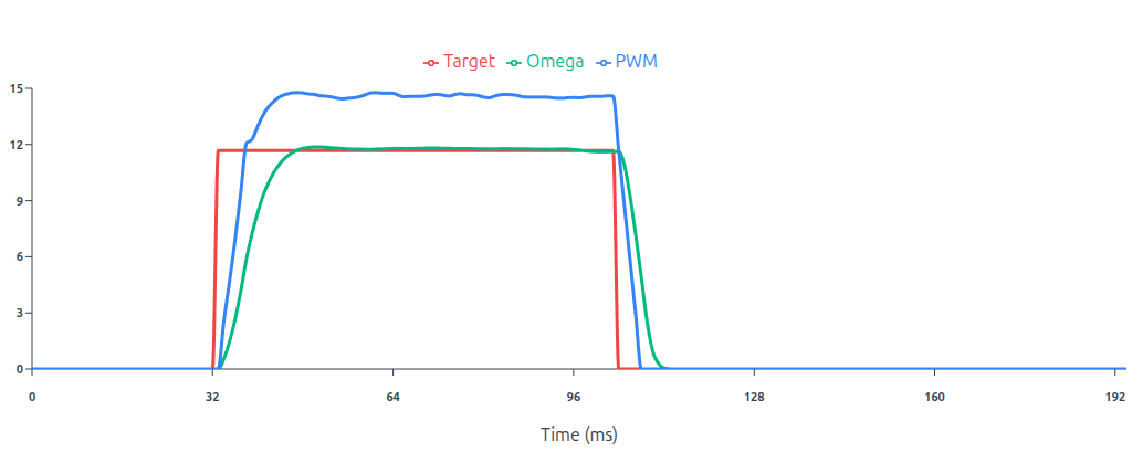
This graph above illustrates a well-tuned PID loop where the Omega (green) tracks the Target (red) with minimal overshoot and stable convergence.
- Acceleration Feedforward: Unlike the classic version, this system sees the 0.4 m/s target step and immediately calculates the torque (current) required to accelerate that mass. It injects this into the output before an error even exists.
- Stribeck Friction Modeling: By modeling the friction curve, the controller pre-compensates for the break-away force needed at 0 velocity, effectively neutralizing the friction so the PID only has to handle minor disturbances.
- Velocity-to-Current Cascade The outer velocity loop doesn’t talk to the motor voltage directly; it tells the inner loop, I need X amount of current. The inner current loop is much faster, ensuring the motor torque actually matches what the velocity loop (and feedforwards) requested, leading to the near-perfect step response.
Cascaded control architecture
The outer loop calculates a current setpoint, which is then tracked by the inner PI loop. This allows for direct torque control and faster disturbance rejection.
CASCADEDEnables or disables the Cascaded Loop.
Loop Constraints & Calibration
INNER_LIMITThe maximum allowable PWM duty cycle for the current loop output.CURRENT_LEFT_MULTIPLIER/CURRENT_MULTIPLIER_RIGHTA multiplier applied to the raw current sensor reading to match the scale of the current reference setpoint.CURRENT_OMEGA_K_LEFT/CURRENT_OMEGA_K_RIGHTThese values are added to or subtracted from the base multiplier, scaled linearly as speed increases from 0 to ω max. This corrects for drift or gain changes in the current sensing circuit at high rotational speeds.
PI Controller
CURRENT_KPThe proportional term for the inner PI loop, reacting to the immediate difference between the current reference and the measured current.CURRENT_KIThe integral term for the inner PI loop. It accumulates error over time to ensure the measured current accurately tracks the current reference setpoint.
Armature Resistance
These parameters model the physical characteristics of the DC motors. Accurate modeling here improves the feedforward performance and odometry estimation.
R_ARMUsed to calculate the voltage drop required to drive a specific current. ( 𝑉 = 𝐼 × 𝑅 )
Torque Constant & Back-EMF Model
| Parameter | Type | Description | Default |
|---|---|---|---|
| LEFT_KT | float | Torque Constant for Left Motor | 0.016 |
| LEFT_KT_W | float | Torque Constant Omega Compensation Left | -0.008 |
| RIGHT_KT | float | Torque Constant for Right Motor | 0.016 |
| RIGHT_KT_W | float | Torque Constant Omega Compensation Right | -0.008 |
In the cascaded control mode, the system estimates the Back Electromotive Force (Back-EMF) generated by the spinning motor. This voltage estimate is added to the controller output as a feedforward term, allowing the PID loop to focus solely on driving the required current rather than overcoming the motor’s generated voltage.
LEFT_KT/RIGHT_KTThe constant used to calculate the Back-EMF voltage from the motor’s angular velocity (ω) when the motor is beginning to spin.LEFT_KT_W/RIGHT_KT_WA compensation factor that adjusts the Torque Constant linearly as the motor speed increases toward its maximum.
Typical Values
CASCADED: True
INNER_LIMIT: 240
CURRENT_KP: 8.0
CURRENT_KI: 6.0
CURRENT_MULTIPLIER_LEFT: 4.8
CURRENT_MULTIPLIER_RIGHT: 4.8
CURRENT_OMEGA_K_LEFT: -2.4
CURRENT_OMEGA_K_RIGHT: -2.4
R_ARM: 2.0
LEFT_KT: 0.016
LEFT_KT_W: -0.008
RIGHT_KT: 0.016
RIGHT_KT_W: -0.008
| Parameter | Type | Description | Default |
|---|---|---|---|
| OUTER_FEEDFORWARD | boolean | Enable Outer Loop Feed-forward | False |
| K_FF_VEL | float | Velocity Feed-forward / s | 0.16 |
| K_FF_ACCEL | float | Acceleration Feed-forward / s² | 0.12 |
Physics Feed-Forwards (Outer Loop)
Adds predictive control signals to the outer loop. Instead of waiting for an error to develop (as PID does), feed-forward uses the physics of the robot to guess the required output for a given target velocity and acceleration. This significantly reduces lag during rapid speed changes.
OUTER_FEEDFORWARDEnables or disables the physics-based feed-forward terms in the outer control loop.
Coefficients
K_FF_VELAdds output power proportional to the target velocity to compensate for kinetic friction.K_FF_ACCELAdds output power proportional to the requested acceleration.
Typical Values
OUTER_FEEDFORWARD: True
K_FF_VEL: 0.12
K_FF_ACCEL: 0.08
| Parameter | Type | Description | Default |
|---|---|---|---|
| OUTER_SCV | boolean | Enable SCV if not deadzone will be used | False |
| STATIC_KICK | float | Initial Kick in Volts | 6.0 |
| COULOMB_RUN | float | Minimum energy for motor to turn in Volts | 3.0 |
| STRIBECK_WIDTH | float | Statick Kick Decay rate | 64 |
| VISCOUS_FRICTION | float | Viscous Friction Coefficient | 0.001 |
| VISCOUS_FRICTION_LIMIT | float | Viscous Friction Limit | 1.2 |
| EB_FF_LIMIT | float | Calculated BEMF Limit in Volts | 12.0 |
| SCV_OMEGA_THRESHOLD | float | Below this threshold SCV will not be triggered | 0.05 |
| SCV_LATCH_THRESHOLD | float | Below this threshold Static kick will not be triggered | 1.0 |
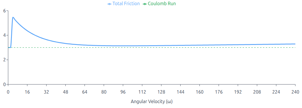
The graph above shows the total added friction volts as a function of angular velocity. STATIC_KICK = 6V, STRIBECK_WIDTH = 16, COULOMB_RUN = 3V, VISCOUS_FRICTION = 0.001, SCV_LATCH_THRESHOLD = 2 rad/s
Advanced Friction Compensation (Stribeck Model)
This model implements a comprehensive physics-based friction model entirely within the outer PID loop. By preemptively calculating the voltage required to overcome mechanical resistance, it allows the controller to break stiction and maintain motion without waiting for integral error to build up.
The model dynamically calculates a feedforward voltage that decays exponentially from a high Static Kick down to a steady Coulomb level as speed increases, while simultaneously adding a linear Viscous term.
To prevent jitter at very low speeds, the model features a specific gating mechanism controlled by
SCV_LATCH_THRESHOLD.
- Above Threshold: The full Stribeck model is active. (Static Kick + Coulomb + Viscous)
- Below Thrshold: The aggressive static kick and viscous terms are disabled. Only the constant
COULOMB_RUNvoltage is applied. This prevents low-speed oscillation while maintaining sufficient holding force to keep the robot ready to move.
Parameters
OUTER_SCVEnables SCV Model. IfFalsesimple dead zones are applied.STATIC_KICKThe high initial voltage spike required to break static friction (stiction) when starting motion. This is the peak value of the exponential curve.COULOMB_RUNThe floor voltage required to keep the motor spinning at the lowest possible non-zero speed. When velocity is below the latch threshold, this is the only voltage applied.STRIBECK_WIDTHThe exponential decay rate. A higher value causes the Static Kick to fade away more sharply as the robot accelerates, transitioning quickly to the Coulomb level.VISCOUS_FRICTIONThe linear friction coefficient. Accounts for resistance that scales with speed. (e.g., grease viscosity, floor drag)SCV_LATCH_THRESHOLDThe low-speed safety gate. When velocity (ω) is below this value, the Static Kick and Viscous terms are disabled to prevent oscillation, leaving only the steady Coulomb Run voltage.VISCOUS_FRICTION_LIMITHard limits the maximum voltage contribution from the viscous friction term.EB_FF_LIMITLimits the maximum voltage that the Back-EMF estimator is allowed to inject into the controller.SCV_OMEGA_THRESHOLDZero-Velocity Noise Gate. A cutoff value below which the target velocity (ω) is mathematically treated as exactly 0.0.
| Parameter | Type | Description | Default |
|---|---|---|---|
| LEFT_FORWARD_DEADZONE | int16 | Left Motor Forward Deadzone | 0 |
| LEFT_REVERSE_DEADZONE | int16 | Left Motor Reverse Deadzone | 0 |
| RIGHT_FORWARD_DEADZONE | int16 | Right Motor Forward Deadzone | 0 |
| RIGHT_REVERSE_DEADZONE | int16 | Right Motor Reverse Deadzone | 0 |
Typical Values
OUTER_SCV: True
STATIC_KICK: 0.8
COULOMB_RUN: 0.2
STRIBECK_WIDTH: 2.1
VISCOUS_FRICTION: 0.064
VISCOUS_FRICTION_LIMIT: 1.2
EB_FF_LIMIT: 12.0
SCV_OMEGA_THRESHOLD: 0.05
SCV_LATCH_THRESHOLD: 1.0
LEFT_FORWARD_DEADZONE: 12
LEFT_REVERSE_DEADZONE: 12
RIGHT_FORWARD_DEADZONE: 12
RIGHT_REVERSE_DEADZONE: 12
| Parameter | Type | Description | Default |
|---|---|---|---|
| TRIM_GAIN | float | Overall Gain Factor | 1.0 |
| TRIM_MOTOR_K | float | Motor constant for output calculation | 1.0 |
| TRIM_CONSTANT | float | Trim value for motor output | 1.0 |
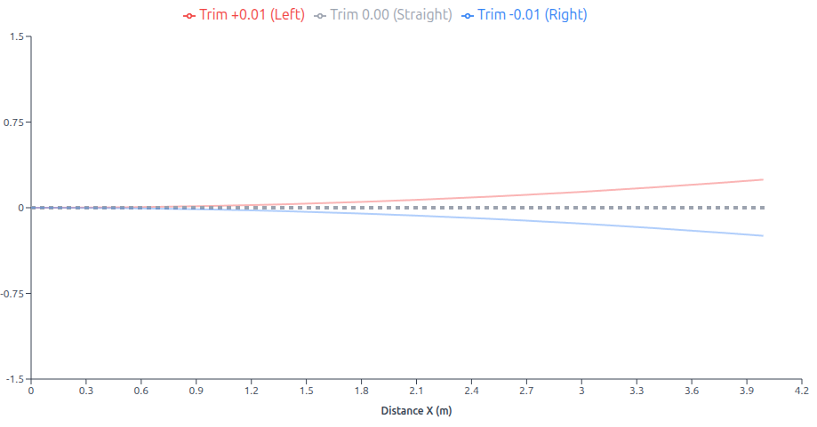
This graph above demonstrates how the TRIM parameter affects differential drive robot trajectory: a positive TRIM value (+0.01) increases the left motor constant relative to the right, causing the robot to curve left (red path), while a negative TRIM value (-0.01) has the opposite effect, curving the robot right (blue path), and zero TRIM (0.00) results in straight-line motion (gray path) with equal motor constants.
Trim Model
In the context of motor control, the motor constant is a proportionality factor that relates the input voltage to the output speed or torque. By adjusting the motor constant, we can compensate for differences in motor performance, such as variations in motor efficiency or mechanical load. The trim parameter, on the other hand, is used to introduce a small offset to the motor’s output. This can be helpful in compensating for slight misalignments in the robot’s mechanical structure or differences in motor characteristics.
In the given equations:
MotorConstantLeft = (GAIN + TRIM) / MOTOR_CONSTANT;
MotorConstantRight = (GAIN - TRIM) / MOTOR_CONSTANT;
The MotorConstantLeft and MotorConstantRight values are used to multiply the algorithm output (typically from a PID controller) to determine the appropriate PWM values for the left and right motors. These adjusted motor constants account for variations in motor performance and mechanical factors, ensuring precise and coordinated motor control.
MotorConstantLeftandMotorConstantRightare the adjusted motor constants for the left and right motors.TRIM_GAINis a global gain factor that scales the overall motor output.TRIM_MOTOR_Kis the nominal motor constant.TRIM_CONSTANTis a small value used to adjust the motor output.
By adjusting the TRIM parameter, we can effectively fine-tune the motor outputs to ensure accurate and precise robot motion, even in the presence of minor variations in motor performance or mechanical alignment.
Typical Values
TRIM_GAIN: 1.0
TRIM_MOTOR_K: 1.0
TRIM_CONSTANT: 0.0
| Parameter | Type | Description | Default |
|---|---|---|---|
| OMEGA_FILTER_TYPE | uint8 | Velocity Filter Type | 1 |
| CURRENT_FILTER_TYPE | uint8 | Current Filter Type | 3 |
| OUTPUT_FILTER_TYPE | uint8 | Output Filter Type | 0 |
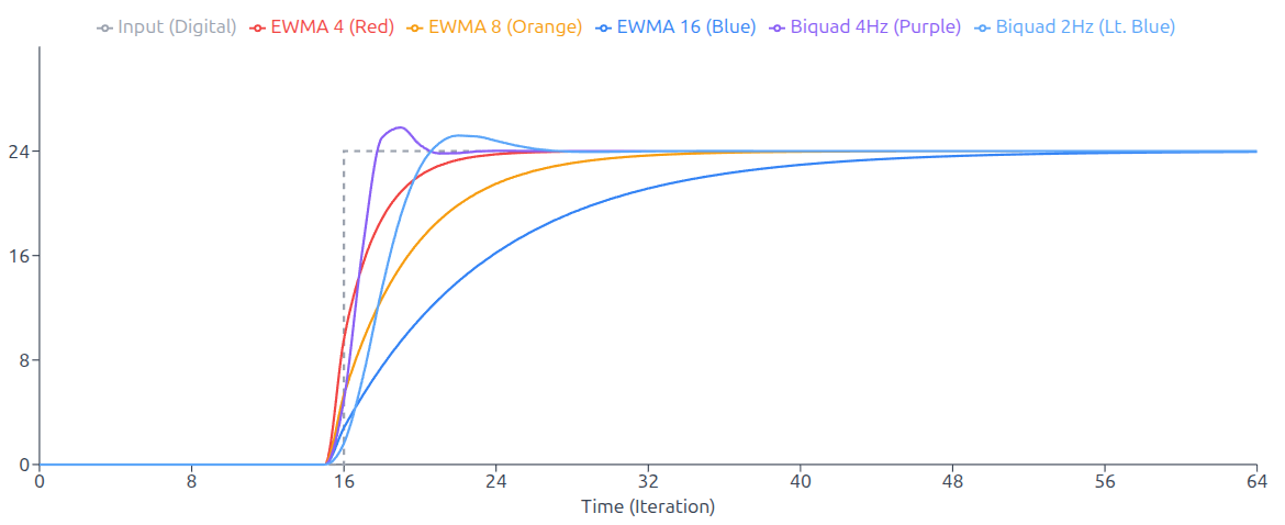
This plot above compares the step response characteristics of five low-pass filters when subjected to a step input from 0 to 24 at iteration 16. Three Exponential Weighted Moving Average (EWMA) filters with window sizes N=4, 8, and 16 are compared against two second-order Biquad filters designed for a 20Hz sampling rate with cutoff frequencies of 2Hz and 4Hz.
The EWMA4 filter provides the fastest response but with the least smoothing, while EWMA16 offers the smoothest output at the cost of slower settling time. The BiQuad filters demonstrate superior frequency response control, with the 2Hz variant providing smooth steady-state performance and the 4Hz variant offering a balance between responsiveness and filtering effectiveness.
Velocity Measurement Filter
This filter processes the raw velocity feedback (ω) calculated from the encoders. Filtering here is critical because differentiation of encoder ticks often produces discrete, step-like noise that can destabilize the PID loop.
| Name | ID | Type | Details |
|---|---|---|---|
| NONE | 0 | N / A | No Filter |
| EWMA4 | 1 | EWMA | Exponentially Weighted Moving Average. Low lag, light smoothing (Last 4 samples) |
| EWMA8 | 2 | EWMA | Exponentially Weighted Moving Average (Last 8 samples) |
| EWMA16 | 3 | EWMA | Exponentially Weighted Moving Average (Last 16 samples) |
| BIQUAD_20HZ_2HZ | 4 | Bi-Quad Filter | 2nd Order Low-Pass Filter. Cutoff at 2Hz. (assuming 20Hz loop) aggressive noise rejection |
| BIQUAD_20HZ_4HZ | 5 | Bi-Quad Filter | 2nd Order Low-Pass Filter. Cutoff at 4Hz. |
Filters Explained
- EWMA: (Exponentially Weighted Moving Average) A computationally efficient filter that gives more weight to recent data.
- Pros: Very fast to calculate, good for general noise.
- Cons: Can introduce lag if the window size (4, 8, 16) is too large.
- Bi-Quad: (Biquadratic Filter) A second-order recursive linear filter.
- Pros: Capable of sharp cutoffs (removing specific frequencies) better than EWMA.
- Cons: More complex; incorrect configuration can lead to instability.
Current Measurement Filter
This filter processes the noisy analog data from the current sensors before it enters the inner current loop. High-frequency noise here is common due to PWM switching and brush arcing.
| Name | ID | Filter Type | Details |
|---|---|---|---|
| NONE | 0 | N / A | No Filter |
| EWMA4 | 1 | EWMA | Exponentially Weighted Moving Average (Last 4 samples) |
| EWMA8 | 2 | EWMA | Exponentially Weighted Moving Average (Last 8 samples) |
| EWMA16 | 3 | EWMA | Exponentially Weighted Moving Average (Last 16 samples) |
Output Filter
This filter is applied to the final output of the control loop before it is sent to the motors. It is typically used to sharpen the response or map the linear PID output to a non-linear actuator curve.
| Name | ID | Filter Type |
|---|---|---|
| None | 0 | None |
| TANH | 1 | Tanh |
| SIGM | 2 | Sigmoid |
Output Filter Scalers
| Parameter | Type | Description | Default |
|---|---|---|---|
| TANH_DIV | float | Divider to scale the Tanh input range. Controls curve width. | 2.0 |
| SIGM_DIV | float | Divider to scale the Sigmoid input range. | 10.0 |
The Output Filter applies a non-linear transformation (Hyperbolic Tangent or Sigmoid) to the final
control signal, creating a soft clipping effect that smooths out aggressive commands near the
maximum limit. The shape of this response curve is tunable via divisor parameters (TANH_DIV, SIGM_DIV),
allowing you to adjust how sharply the motor power saturates.
Output Filters Explained
- TANH (Hyperbolic Tangent) A symmetric S-shaped transfer function that creates a soft clip effect. It is linear for small errors but smoothly saturates as the output approaches the limit.
- SIGM (Sigmoid) A non-linear activation function that maps the control signal to a gradual S-curve.
Filter Routing Configuration
This section controls Filter Routing. It determines whether the motor controller uses Raw (noisy, fast) or Filtered (smooth, slightly delayed) sensor data for specific calculations.
For every calculation below, you have a binary choice:
FalseRaw Data: The controller sees the sensor data exactly as it happens. It is instant but can be “jittery” or noisy.TrueFiltered Data: The controller sees a smoothed-out version of the data. It eliminates noise but reacts slightly slower (milliseconds of delay).
| Parameter | Type | Description | Default |
|---|---|---|---|
| VOLTAGE_FILTER | boolean | Use Filtered voltage for Cascaded Loop Calculations | False |
| BEMF_FILTERED_OMEGA | boolean | Use Filtered Omega for Cascaded Loop Calculations | False |
| PID_FILTERED_OMEGA | boolean | Use Filtered Omega for PID Error Calculations | False |
| SCV_FILTERED_OMEGA | boolean | Use Filtered Omega for SCV Model | False |
| CURRENT_OMEGA_FILTER | boolean | Use Filterd Omega for Current Multiplier Compensation | False |
Typical Values
OMEGA_FILTER_TYPE: 1
CURRENT_FILTER_TYPE: 3
OUTPUT_FILTER_TYPE: 0
TANH_DIV: 2.0
SIGM_DIV: 10.0
VOLTAGE_FILTER: True
BEMF_FILTERED_OMEGA: True
PID_FILTERED_OMEGA: True
SCV_FILTERED_OMEGA: True
CURRENT_OMEGA_FILTER: True
| Parameter | Type | Description | Default |
|---|---|---|---|
| AUTO_BIAS | boolean | Auto Bias Enabled | True |
| ADC_SYNC | boolean | ADC Syncronized with PWM. Required for Cascaded Mode | False |
| ADC_MULTIPHASE | boolean | Multi-Phase ADC Measurement. BEMF compensated Mode | False |
| ADC_BIPHASE | boolean | Bi-Phase ADC Measurement | False |
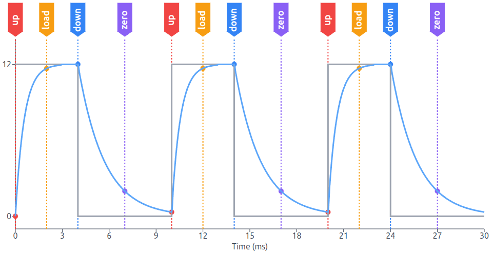
The figure above highlights the synchronization between the PWM control signal and the system’s ADC,
where the marked states (UP, LOAD, DOWN, ZERO) indicate precisely when the ADC triggers a measurement to capture the current value.
ADC & Calibration Configuration
This section controls how the microcontroller calibrates its sensors and synchronizes its analog measurements (ADC) with the motor’s power output (PWM). Correct configuration here is vital for clean current sensing.
AUTO_BIASWhen the robot is stationary (not in motion), the system measures the sensor output to find the zero point, automatically updatingCS_LEFT_OFFSETandCS_RIGHT_OFFSET.ADC_SYNCTriggers the ADC sample exactly in the middle of the PWM ON pulse. This avoids switching noise at the edges. Required for Cascaded Mode.ADC_MULTIPHASEMeasures at ON, OFF, and Middle points to reconstruct the current curve. It integrates the curve but specifically excludes the OFF time readings from the total, compensating for Back-EMF effects.ADC_BIPHASESamples the signal twice: once in the middle of the PWM ON time and once in the middle of the OFF time.
ADC Bias Calibration
| Parameter | Type | Description | Default |
|---|---|---|---|
| CS_LEFT_OFFSET | int16 | Current Sense Calibration Value Left | 0 |
| CS_RIGHT_OFFSET | int16 | Current Sense Calibration Value Right | 0 |
This section contains the static calibration values for the current sensors.
These are hardcoded integer offsets used to zero out the sensors if AUTO_BIAS is
disabled or if fine-tuning is required.
Typical Values
AUTO_BIAS: True
ADC_SYNC: True
ADC_MULTIPHASE: True
ADC_BIPHASE: False
CS_LEFT_OFFSET: 0
CS_RIGHT_OFFSET: 0
| Parameter | Type | Description | Default |
|---|---|---|---|
| AUTO_SYNC | boolean | Enables the automatic timer frequency adjustment logic. | True |
| SYNC_KP | uint16 | How hard the timer corrects for immediate phase errors. | 256 |
| SYNC_KI | uint16 | How strictly the timer compensates for long-term drift (accumulated error). | 4 |
| SYNC_LIMIT | uint16 | The maximum amount the timer period can be changed in a single step. Prevents instability. | 4096 |
| SYNC_INTERVAL | uint8 | Defines how often the sync logic runs (e.g., 8 means check and adjust every 8th loop cycle). | 8 |
| DT_I2C | uint16 | The desired delay between the sync event and the loop start. | 32 |
| DT_THRESHOLD | uint16 | If the phase error is less than this value (in ticks), no adjustment is made. Prevents hunting or jitter. | 2 |
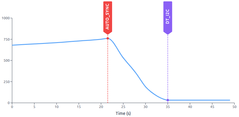
This feature functions as a software-based Phase Locked Loop (PLL). It synchronizes the device’s internal interrupt timer with an external event stream (typically I2C communication packets) to prevent clock drift.
The red AUTO_SYNC marker indicates when the automatic synchronization feature is enabled.
Within a few seconds, the system corrects the phase drift, stabilizing the phase delay to the value
given on DT_I2C.
The Core Concept: Clock Drift Synchronization
Even with high-precision crystals, two separate devices will eventually drift apart. This feature measures the Phase Error (the time difference between when an I2C packet arrives and when the internal loop starts) and dynamically adjusts the Interrupt Timer Frequency to keep them locked together.
The system targets a specific delay DT_I2C rather than zero delay.
This ensures the calculation loop always starts exactly 1ms (32 ticks) after data reception,
guaranteeing fresh data is available without race conditions.
Typical Values
AUTO_SYNC: True
SYNC_KP: 256
SYNC_KI: 4
SYNC_LIMIT: 4096
SYNC_INTERVAL: 8
DT_I2C: 32
DT_THRESHOLD: 2
| Parameter | Type | Description | Default |
|---|---|---|---|
| ODOM_FRAME_ID | string | Sets the frame ID for the odometry data | odom |
| BASE_FRAME_ID | string | Sets the frame ID for the robot’s base frame | base_footprint |
| CMD_VEL_TOPIC | string | Command Topic Name | cmd_vel |
| BROADCAST_TF2 | bool | Enables or disables TF2 broadcast | True |
| PUB_ODOMETRY | bool | Enables or disables odometry data publication | True |
| PUB_JOINTS | bool | Enables or disables joint state publication | True |
| PUB_DIAGNOSTICS | bool | Enables or disables diagnostic data publication | True |
This section defines how the driver interacts with the ROS, including the TF Tree (coordinate frames), Topic Names, and Data Publishing toggles.
Coordinate Frames & TF Tree
These parameters define the naming convention for the robot’s coordinate systems.
The driver uses these IDs when constructing the standard nav_msgs/Odometry packet.
The header.frame_id will be set to ODOM_FRAME_ID and the child_frame_id will be set to BASE_FRAME_ID.
ODOM_FRAME_IDThe driver publishes the transform from this frame to the main frame.BASE_FRAME_IDThe name of the frame for the mobile robot.
Data Publishing Toggles
These booleans act as switches for the driver’s output streams. You can disable specific streams to save bandwidth or avoid conflicts.
BROADCAST_TF2Set toFalseif you are using an external localizer (likerobot_localizationorcartographer) to handle the TF tree.PUB_ODOMETRYDecides if the driver publishesnav_msgs/Odometrymessages containing position and velocity covariance.PUB_JOINTSRequired forrobot_state_publisherto visualize wheel rotation in URDF / RViz.PUB_DIAGNOSTICSDecides if the driver publishesmsg/Diagnostics.msgcontaining battery voltage, error flags, and internal status.
Typical Values
ODOM_FRAME_ID: 'odom'
BASE_FRAME_ID: 'base_footprint'
CMD_VEL_TOPIC: 'cmd_vel_nav'
BROADCAST_TF2: True
PUB_ODOMETRY: True
PUB_JOINTS: True
PUB_DIAGNOSTICS: True
| Parameter | Type | Description | Default |
|---|---|---|---|
| MAIN_AMP_LIMIT | float | Maximum current draw for the main power supply | 3.6 |
| BAT_VOLTS_HIGH | float | Maximum battery voltage | 15.0 |
| BAT_VOLTS_LOW | float | Minimum battery voltage | 6.0 |
| LEFT_AMP_LIMIT | float | Maximum current limit for the left motor | 1.6 |
| RIGHT_AMP_LIMIT | float | Maximum current limit for the right motor | 1.6 |
| INA219_CAL | uint16 | INA219 Calibration Value | 8192 |
This section defines the safety boundaries for your power system. It relies on two different measurement sources: the INA219 Monitoring chip (for total system power) and the Internal Motor Sense (for individual motor software fuses).
MAIN_AMP_LIMITThe maximum allowable current for the entire board (motors + electronics). Uses a Rolling Average Filter to ignore short spikes.BAT_VOLTS_HIGHThe system will disable motor drivers if the battery voltage exceeds this limit.BAT_VOLTS_LOWThe system will disable motor drivers down to protect the system.LEFT_AMP_LIMITA fast-acting safety trip for the left motor channel. If current exceeds this value, the Software Fuse trips and disables the motor drivers.RIGHT_AMP_LIMITA fast-acting safety trip for the right motor channel. If current exceeds this value, the Software Fuse trips and disables the motor drivers.INA219_CALThe raw calibration value loaded into the INA219 chip register to ensure Volts and Amps are reported accurately.
Typical Values
MAIN_AMP_LIMIT: 3.6
BAT_VOLTS_HIGH: 15.0
BAT_VOLTS_LOW: 6.0
LEFT_AMP_LIMIT: 2.4
RIGHT_AMP_LIMIT: 2.4
INA219_CAL: 8192
| Parameter | Type | Description | Default |
|---|---|---|---|
| CROSS_COUPLED_CONTROL | bool | Enable Cross Coupled Control | False |
| CROSS_KP | float | Cross Proportional Coefficient | 4.0 |
| CROSS_K_LEFT | float | Cross Feedback Left Coefficient | 1.0 |
| CROSS_K_RIGHT | float | Cross Feedback Right Coefficient | 1.0 |
This feature improves the robot’s ability to drive in a straight line, especially on uneven terrain. In a standard differential drive robot, the Left and Right motors have separate PID controllers. They don’t talk to each other.
Cross-Coupled Control links the two PID loops together. If the Left wheel falls behind, the controller intentionally slows down the Right wheel to match it. It prioritizes Synchronization over absolute speed.
CROSS_COUPLED_CONTROLEnable disable cross coupled control.CROSS_KPCoupling Stiffness. Determines how strongly the motors are tied together. Higher values create a stiffer virtual shaft but can cause oscillation.CROSS_K_LEFTHow much the Right Error affects the Left Motor. Used to balance asymmetric motors.CROSS_K_RIGHTHow much the Left Error affects the Right Motor.
| Parameter | Type | Description | Default |
|---|---|---|---|
| AUTO_BRAKE | boolean | Auto Brake Enabled | False |
This parameter controls the physical behavior of the H-Bridge when the robot is receiving Zero Velocity commands (idle).
In Coasting Mode ( AUTO_BRAKE: False ), the controller opens all MOSFETs (High-Impedance). The motor spins freely,
and the robot’s inertia will make it roll to a gradual stop.
In Brake Mode ( AUTO_BRAKE: True ), the controller turns on the bottom MOSFETs (Low-Side) for all phases.
This shorts the motor terminals together. Any movement generates Back-EMF, which creates a current loop that fights the motion.
This brings the robot to a stop quickly and makes it hard to push.
AUTO_BRAKE parameter is ignored if MODE1 is enabled in your CONFIG_FLAGS.
Typical Values
CROSS_COUPLED_CONTROL: True
CROSS_KP: 4.0
CROSS_K_LEFT: 1.0
CROSS_K_RIGHT: 1.0
AUTO_BRAKE: False
| Parameter | Type | Description | Default |
|---|---|---|---|
| ROS2RPI_CONFIG | uint8 | Configuration for the ROS2RPI board (if used) | 0x00 |
| I2C_ADDRESS | uint8 | I2C address of the card | 0x3C |
| I2C_ENABLED | bool | Enables or disables I2C communication. For development only. | True |
| DEBUG | bool | Enables or disables debug mode | False |
| RTC_TRIM | uint32 | Real-Time Clock trim value | 0x7FFF |
| ALLOWED_SKIP | uint8 | Command timeout in units of 1 / UPDATE_RATE. | 3 |
| MONITOR_RATE | uint8 | Rate at which current sensor data is monitored | 100 |
| MAX_IDLE_SECONDS | uint16 | Maximum idle seconds before entering hibernate mode | 3600 |
This section covers the settings for ROSRider board.
I2C_ADDRESSThe 7-bit address used by the host to communicate with this card.I2C_ENABLEDThis is primarily for development / debugging. Disabling this will prevent the driver from communicating with the board.DEBUGEnables internal verbose logging or specific testing behaviors.RTC_TRIMA calibration value for the Real-Time Clock (RTC). This parameter adjusts the internal oscillator to compensate for drift, ensuring time-based calculations remain accurate over long periods.ALLOWED_SKIPThe ROSRider employs a command timeout mechanism to ensure safe operation and prevent unintended movement. This mechanism monitors the frequency of incoming commands from the host computer. If the system fails to receive a command within a specified time frame, it enters a state that restrains movement. TheALLOWED_SKIPparameter in the ROSRider configuration determines the maximum number of consecutive command cycles that can be skipped before triggering the timeout. This value, when multiplied by the inverse of theUPDATE_RATE(measured in milliseconds), sets the overall timeout duration. For instance, ifALLOWED_SKIPis set to 3 and theUPDATE_RATEis 20Hz, the timeout duration would be 150 milliseconds.MONITOR_RATEDefines how frequently (in Hz) the background task checks monitoring sensors.MAX_IDLE_SECONDSThe duration of inactivity (no commands received) allowed before the board enters a low-power Hibernate mode to save battery.ROS2RPI_CONFIGWhen operating the ROSRider card in conjunction with the ROS2RPI card on a Raspberry Pi platform, the driver provides the capability to transmit commands to the ROS2RPI card. This functionality is particularly valuable for controlling peripheral devices, such as lidar units, during the driver initialization sequence. If the ROSRider card is deployed independently (standalone configuration), set this parameter to 0.
| Hat Command | Description |
|---|---|
| 0x00 | No Command |
| 0x0F | ROSRider ON, Serial Routed to DEBUG |
| 0x33 | ROSRider ON, LIDAR ON, Serial Routed to LIDAR |
For configurations involving the ROS2RPI card, refer to the ROS2RPI documentation for appropriate parameter selection.
Typical Values
ROS2RPI_CONFIG: 0x33 # 0x00 # 0x0F # 0x33
I2C_ADDRESS: 0x3c
I2C_ENABLED: True
DEBUG: False
RTC_TRIM: 0x7FFF
ALLOWED_SKIP: 3
MONITOR_RATE: 100
MAX_IDLE_SECONDS: 1800
Next Chapter: Procedures
Copyright © 2026, ACADA Robotics • https://acada.dev